Insert turning identification code - Mitsubishi Materials - milling insert nomenclature
Chip thickness is directly proportional to the angle of attachment, if the angle of attachment increases consequently the thickness increases but the width decreases, this cutting condition also affects the direction of the chip output.
Coatings provide thermal stability to the carbide inserts, allowing them to withstand high temperatures without losing their hardness or deforming. This enables higher cutting speeds and feeds, increasing productivity and efficiency.
The trochoidal milling is a processing method that is used by using a radial engagement of the cutter combined with a higher cutting speed. Read more...
The choice of the ideal insert for the turning processing is the first step towards optimising the production process, this passes through the evaluation of some primary and other secondary parameters that are also important.
Coatings reduce the friction between the carbide inserts and the workpiece, resulting in smoother cutting action. This minimizes heat generation and prevents the build-up of chips on the cutting edge, leading to improved chip evacuation and better surface finish.
Substrate or hard metal base, coating with PVD or CVD technologies and cutting edge geometry, create the ideal combinations for the processes required.
Another important factor to evaluate which is often underestimated is the corner radius of the cutting edge, for a correct application this should generally not be less than 2/3 of the "ap" cutting depth. In addition, factors such as surface finish, chip formation and cutting edge strength are linked to the insert radius.
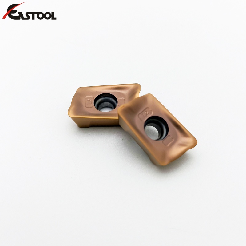
The purpose of coating carbide inserts is to enhance their performance, durability, and cutting capabilities. Coatings provide several benefits that contribute to the overall effectiveness of carbide inserts. Here are the main objectives of coating carbide inserts:
The choice of the ideal insert for the turning processing passes through the evaluation of some primary and other secondary parameters that are also important.
The type of machining also affects the size of the insert, this must be chosen according to the depth of "ap" pass and the type of insert used.
The figure in Tab.1 below identifies the ideal insert shape according to the profile that have to be executed, combined with Tab.2 which identifies the attachment angle or recording that affect the chip formation.
By improving wear resistance, reducing friction, and enhancing heat resistance, coatings significantly extend the tool life of carbide inserts. This reduces the frequency of tool changes, increases production uptime, and lowers tooling costs.
Enhanced Performance in Specific Applications: Different coatings are designed to excel in specific machining applications or materials. For example, some coatings are optimized for high-speed machining, while others are suitable for cutting high-hardness or high-temperature alloys. Coatings can be tailored to specific requirements to achieve optimal performance. Overall, the purpose of coating carbide inserts is to improve their performance, increase their durability, and optimize their cutting capabilities. Coatings enhance wear resistance, reduce friction, improve heat resistance, extend tool life, and enable better performance in various machining applications.
For an optimal chip control, the insert’s field of application must be within the graphs in the catalogue, see example Tab 3.
Coatings increase the hardness of the carbide inserts, making them more resistant to wear. This allows the inserts to withstand the high forces and temperatures generated during cutting operations, resulting in longer tool life and reduced tool replacement frequency.
In Tab.5 there is an extract of the SAU catalog where the maximum feeds recommended are indicated according to the insert radius and theoretically approximate (but sufficiently reliable) the roughness that is obtained in relation between radius insert "rɛ" and feed "fn".
Coated carbide inserts can withstand higher cutting speeds and feed rates due to their increased hardness and reduced friction. This results in faster machining times and higher productivity.
Generally the small radius has a weak cutting edge and is used for finishing operations with low cutting depth, where there are vibration problems and a better chip control. On the contrary, the large radius is a symbol of the sharpness of the cutting edge, great cutting depths and high feeds, this causes increased cutting forces and therefore risk of vibration.


 18581906093