
Turning & Threading Tools - ISCAR Tools - PDF Catalogs - iscar turning insert
The cross-section type of a milling insert refers to the shape of its cutting edge when viewed from a perpendicular angle. It influences the insert's cutting action and performance.
American National Standard ANSI B212.4-2002 covers the identification system for indexable-type inserts for both single-point and multiple-point cutting tools. It was published on October 29, 2002. The earlier editions of the standard are:
The sixth position is a significant one- or two-digit number indicating the number of sixteenths of an inch in the thickness of the insert. It is a one-digit number when the number of sixteenths of an inch in the thickness is a whole number: 1 – 1 ⁄ 16"; 2 – 1 ⁄ 8"; 3 – 3 ⁄ 16"; 4 – 1 ⁄ 4"; 5 – 5 ⁄ 16"; 6 – 3 ⁄ 8"; 7 – 7 ⁄ 16"; 8 – 1 ⁄ 2"; 9 – 9 ⁄ 16"; 10 – 5 ⁄ 8".
ANSI B212.4-2002 standard added one more capital letter O, which denotes other relief angles for new designs of indexable inserts.
Conditioning of the cutting edge, such as a honing or chamfering, to make it stronger and less susceptible to chipping. A chamfer is a bevel on the tool’s cutting edge; the angle is measured from the cutting face downward and generally varies from 25° to 45°. Honing is the process of rounding or blunting the cutting edge with abrasives, either manually or mechanically.
Inserts selection depends on workpiece material, chip control, surface finish, tool life, and the machine tool’s power and torque requirements. One of the commonly used indexable inserts for general turning is CNMG 432.
The cutting-edge length of a milling insert is an important factor that directly affects the insert's cutting performance and efficiency.
Due to the magazine’s space limitations, the authors provide the following tables showing most popular Kennametal’s indexable inserts only for general turning of steel, cast iron, and nonferrous alloys. These tables don’t cover all Kennametal chip breakers. (Figure 4 and Figure 5 also show Kennametal Inc. insert identification system and chip breaker identification system respectively.)
If you've ever ventured into the world of milling, you've likely come across the term "ISO code" in reference to milling inserts. But what exactly does this code mean? What information does it convey? Understanding the milling insert ISO code is crucial for selecting the right tool for your milling operations and achieving optimal results.
The thickness of an insert is crucial for its strength and stability during the cutting process.A thicker insert excels under heavy loads, enhancing performance and minimizing the risk of cutting edge chipping.
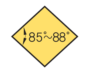
The relief angle for a milling insert is of paramount importance in achieving efficient and successful machining operations.
Imaginary circle that touches all sides of an insert. Used to establish size. Measurements are in fractions of an inch and describe the diameter of the circle.
On rectangular and parallelogram inserts, the width and length dimensions are used in place of the I.C. A two-digit number designates the sizes of these inserts. The first digit indicates the number of eighths of an inch in the width and the second digit indicates the number of fourths of an inch in the length of the insert.
Tolerance refers to the allowable variation in dimensions or measurements of a manufactured part. In the context of milling inserts, the tolerance class specified in section 3 of the ISO code helps determine the level of accuracy and consistency of the insert's dimensions.
The fourth position is a capital letter denoting differences in design of insert, such as the existence of fixing holes, countersinks and special features on rake surfaces. There are 15 standard types in design as follows (Figure 3):
A longer cutting-edge length allows for a larger contact area between the insert and the workpiece, resulting in increased productivity and improved material removal rates. It enables the insert to engage with a greater surface area of the material, reducing the number of passes required to complete a machining operation.
Edmund Isakov, Ph.D., is a consultant, writer and frequent CTE contributor. He is the author of the books “Mechanical Properties of Work Materials” (Modern Machine Shop Publications, 2000); “Engineering Formulas for Metalcutting” (Industrial Press, 2004); “Cutting Data for Turning of Steel” (Industrial Press, 2009); the CD-ROM “International System of Units (SI)” (Industrial Press, 2012); and the software “Advanced Metalcutting Calculators” (Industrial Press, 2005). For more information, call (561) 369-4063 or visit www.edmundisakovphd.com.
There are 16 standard shapes of indexable inserts, and each shape is identified by a capital letter as follows (Figure 1):
Therefore, selecting the appropriate cutting-edge length is crucial in achieving optimal cutting performance, maximising productivity, and ensuring cost-effective milling operations.
The seventh position indicates the cutting point configuration: a radius or a facet. In the case of a radius, the number indicates how many of 1 ⁄ 64 of an inch in the radius: 0 – sharp corner (0.002" max. radius); 0.2 – 0.004"; 0.5 – 0.008"; 1 – 1 ⁄ 64"; 2 – 1 ⁄ 32"; 3 – 3 ⁄ 64"; 4 – 1 ⁄ 16"; 5 – 5 ⁄ 64"; 6 – 3 ⁄ 32"; 7 – 7 ⁄ 64"; 8 – 1 ⁄ 8"; 10 – 5 ⁄ 32"; 12 – 3 ⁄ 16" 14 – 7 ⁄ 32" = 14; 16 – 1 ⁄ 4"; X – Any other corner radius.
It determines whether the insert is designed for right-hand (clockwise) or left-hand (anti-clockwise) rotation during milling operations.
It begins with a letter that indicates the insert's shape, such as R for round, S for square, T for triangular, D for diamond-shaped, or C for rhombic.
Properties of a material that reveal its elastic and inelastic behavior when force is applied, thereby indicating its suitability for mechanical applications; for example, modulus of elasticity, tensile strength, elongation, hardness and fatigue limit.
The mathematical expression denoting one of several parameters that describe surface texture (same as average roughness Ra). Average roughness is the arithmetic average height deviation of the measured surface profile from the profile centerline. See surface texture.
The nose radius of a milling insert holds significant importance in achieving precise and efficient machining operations whilst being able to apply a radius to your cut. Smaller radius tend to be more suitable for finer cuts/finishing whilst larger radius are better for heavy metal removal due to the strength of the insert corner.
By carefully selecting and applying the appropriate edge preparation techniques, machinists can achieve improved machining performance, productivity, and tool longevity, while also maintaining high-quality surface finish and dimensional accuracy.
The hand of a milling insert refers to the orientation or direction of the insert's cutting edge and its corresponding shape.
Tool that cuts a sloped depression at the top of a hole to permit a screw head or other object to rest flush with the surface of the workpiece.
Substances having metallic properties and being composed of two or more chemical elements of which at least one is a metal.
It is a two-digit number carried to one decimal place when it is not a whole number: 1.2 – 5 ⁄ 64"; 1.5 – 3 ⁄ 32"; 2.5 – 5 ⁄ 32"; 3.5 – 7 ⁄ 32".
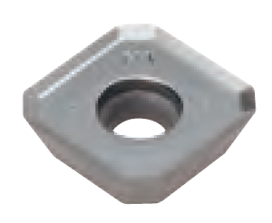
Replaceable tool that clamps into a tool body, drill, mill or other cutter body designed to accommodate inserts. Most inserts are made of cemented carbide. Often they are coated with a hard material. Other insert materials are ceramic, cermet, polycrystalline cubic boron nitride and polycrystalline diamond. The insert is used until dull, then indexed, or turned, to expose a fresh cutting edge. When the entire insert is dull, it is usually discarded. Some inserts can be resharpened.
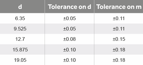
Tolerances on dimensions (± from nominal) are denoted by letters A, B and T. Dimension A is the nominal inscribed circle (I.C.) of the insert. Dimension T is the thickness of the insert. For pentagon, triangle and trigon shapes, dimension B is the insert height, i.e., the distance between one side and the opposite corner (Figure 2).
About the Authors: Edmund Isakov, Ph.D., is a consultant, writer, and frequent CTE contributor. He is the author of four books “Mechanical Properties of Work Materials” (Modern Machine Shop Publications, 2000); “Engineering Formulas for Metalcutting” (Industrial Press, 2004); “Cutting Data for Turning of Steel” (Industrial Press, 2009); “International System of Units (SI)” the CD-ROM (Industrial Press, 2013); and the software “Advanced Metalcutting Calculators” (Industrial Press, 2005). For more information, call (561) 369-4063, or email: edmundisakov9701@comcast.net. Shi ‘Steve’ Chen is Manager Product Engineering Turning at Kennametal Inc. For more information, call (724) 539-5321, or email: Shi.Chen@Kennametal.com
Armed with this knowledge, you're ready to decode the milling insert ISO code and unlock the potential of your milling endeavours.
It plays a crucial role in chip formation, tool life, cutting forces, and surface finish. Understanding the influence of the relief angle and selecting the appropriate one can greatly enhance machining performance, productivity, and the quality of the finished product.
Common cross-section types include square, round, triangle, rhombic, and pentagonal. Machinists should consider the cross-section type when selecting inserts to ensure optimal cutting capabilities and chip evacuation for their specific machining tasks and materials.
It will be a two-digit number carried to one decimal place when it is not a whole number: 1.2 – 5 ⁄ 32"; 1.5 – 3 ⁄ 16"; 1.8 – 7 ⁄ 32"; 2.5 – 5 ⁄ 16".
Therefore, selecting the appropriate thickness is essential for achieving optimal cutting performance, productivity, and the desired quality of the machined components.
Additionally, tight tolerances enable interchangeability within a tooling system, minimising downtime. They also impact tool life and performance, as well as surface finish and accuracy.
The 10th position is only used if there are letters in the seventh position. It will be a significant number representing the nominal sixty-fourths of an inch in length of the primary facet: 1 – 1 ⁄ 64"; 2 – 1 ⁄ 32"; 3 – 3 ⁄ 64"; 4 – 1 ⁄ 16"; 5 – 5 ⁄ 64"; 6 – 3 ⁄ 32"; 7 – 7 ⁄ 64"; 8 – 1 ⁄ 8"; 9 – 9 ⁄ 64"; 10 – 5 ⁄ 32".
The radius can also impact the insert's cutting forces, chip control, tool life, and surface finish. Careful consideration of the appropriate nose radius based on the specific machining requirements and materials is crucial for achieving optimal performance, tool longevity, and surface finish in milling operations.
Workpiece is held in a chuck, mounted on a face plate or secured between centers and rotated while a cutting tool, normally a single-point tool, is fed into it along its periphery or across its end or face. Takes the form of straight turning (cutting along the periphery of the workpiece); taper turning (creating a taper); step turning (turning different-size diameters on the same work); chamfering (beveling an edge or shoulder); facing (cutting on an end); turning threads (usually external but can be internal); roughing (high-volume metal removal); and finishing (final light cuts). Performed on lathes, turning centers, chucking machines, automatic screw machines and similar machines.
Any machining process used to part metal or other material or give a workpiece a new configuration. Conventionally applies to machining operations in which a cutting tool mechanically removes material in the form of chips; applies to any process in which metal or material is removed to create new shapes. See metalforming.
Whether you're a seasoned machinist looking to expand your knowledge or a newcomer to the world of milling seeking clarity, this guide is here to demystify the milling insert ISO code. We'll explore how this code provides vital information about the insert's geometry, material, and cutting characteristics. By the end, you'll be equipped with the knowledge to decode and interpret these codes, empowering you to select the perfect milling inserts to optimise your machining processes.
The edge preparation of a milling insert refers to the intentional modification of the cutting edge before its use in machining operations. It involves applying specific treatments or coatings to enhance the insert's performance and durability.
Space provided behind a tool’s land or relief to prevent rubbing and subsequent premature deterioration of the tool. See land; relief.
According to ANSI B212.4-2002 standard, identification of the indexable insert includes 10 positions denoted by a capital letter. Each position (from 1 to 10) defines a characteristic of the insert in the following order:
Nine relief angle values have been described in ANSI B212.12-1991 standard. These angles are the difference from 90° measured in a plane normal to the cutting edge generated by the angle between the flank and top surface of the insert. Each relief angle is denoted by a capital letter as follows:
By unravelling the meanings behind each section, machinists can confidently select the appropriate milling inserts, ensuring compatibility with their machining setup and achieving desired outcomes in terms of performance, precision, and tool longevity.
The tolerance of a milling insert is important for several reasons. Firstly, it ensures a proper fit and compatibility with the toolholder, promoting stable and secure clamping during machining. Secondly, precise tolerances contribute to dimensional accuracy, allowing for consistent and reliable machining results.
Space provided behind the cutting edges to prevent rubbing. Sometimes called primary relief. Secondary relief provides additional space behind primary relief. Relief on end teeth is axial relief; relief on side teeth is peripheral relief.
The chip breaker of a milling insert refers to a specially designed geometry on the insert's face and cutting edge that helps control and shape the formation of chips during the machining process.
There are 14 tolerance classes that control the indexability of the inserts. Each class is denoted by a capital letter. Letters for tolerances are A, B, C, D, E, F, G, H, J, K, L, M, U and N.
Angle of inclination between the face of the cutting tool and the workpiece. If the face of the tool lies in a plane through the axis of the workpiece, the tool is said to have a neutral, or zero, rake. If the inclination of the tool face makes the cutting edge more acute than when the rake angle is zero, the rake is positive. If the inclination of the tool face makes the cutting edge less acute or more blunt than when the rake angle is zero, the rake is negative.
The fifth position is a significant one- or two-digit number indicating the size of the inscribed circle (I.C.) for all inserts having a true I.C. such as Round, Square, Triangle, Trigon, Pentagon, Hexagon, Octagon, and Diamond. This position designates the number of eighths of an inch in the nominal size of the I.C. It will be a one-digit number when the number of eighths of an inch in the I.C. is a whole number: 1 – 1 ⁄ 8"; 2 – 1 ⁄ 4"; 3 – 3 ⁄ 8"; 4 – 1 ⁄ 2"; 5 – 5 ⁄ 8"; 6 – 3 ⁄ 4"; 7 – 7 ⁄ 8";
For all other polygons, dimension B is the distance, measured along the bisector of the rounded off corner angle and a gage roll of nominal I.C. size tangent to the two sides opposite the corner (Figure 2). For example, if a tolerance letter is H, tolerances on dimensions (± from nominal) are: 0.0005" on dimension A, 0.0005" on dimension B and 0.001" on dimension T.
Understanding the milling insert ISO code is like deciphering a secret language that holds the key to successful milling operations and tool selection.
In case of a facet, two letters are used. The first letter designates the facet angle: A – 45°; D – 60°; E – 75°; G – 87°; P – 90°; Z – Any other facet angle. The second letter designates the facet clearance angle:
This letter gives a quick visual cue about the overall form of the insert. By looking at the first letter of the milling insert ISO code, machinists can get an initial understanding of the insert's shape, which plays a significant role in determining its specific applications and cutting capabilities.


 18581906093